
EXPANSIONS · ADQUIO BUILDING OS
More signals. The same control system.
Expand your installation’s inputs, outputs, relays and temperature measurement points with modules that integrate through Modbus RTU. Choose what each control panel needs and connect those signals to the Adquio ecosystem.
A module for every requirement, within a common architecture.
SIGNALS · ACTUATORS · TEMPERATURE

Adquio Multi IOs
Mixed signals, relays and temperature in a single module.
Choose by signal
Digital, analogue, relay or temperature: add the right control points.
Distribute field connections
Place modules near the equipment and connect them to the controller through the bus.
Expand in stages
Combine multifunction and specialised modules as the installation grows.
Put every data point to use
Use readings and states for automation, visualisation and supervision.
The complete range, organised around what you need to connect
Seven modules with different roles. Combine a multifunction expansion with specialised modules, or start with a dedicated module for the signal you need.
Mixed signals and relays
Adquio Multi IOs
Combine signal acquisition, regulation, switching and temperature measurement in one module. An option for HVAC equipment and machines with varied requirements.
8 configurable A/D inputs · 4 digital outputs · 4 analogue outputs · 5 relays · 4 PT1000
When to choose it: When the project needs several signal types and relay contacts in one device.
More control points
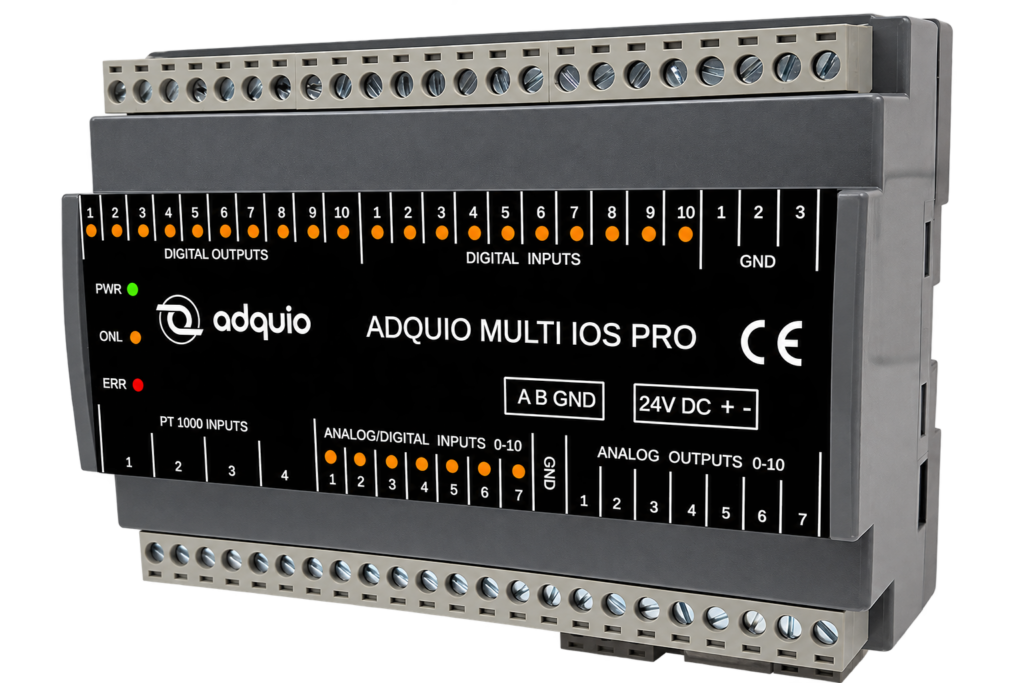
Adquio Multi IOs Pro
Combine configurable inputs, dedicated digital inputs, digital and analogue outputs, and temperature measurement for control panels with a higher density of signals.
7 configurable A/D inputs + 10 digital inputs · 10 digital outputs · 7 analogue outputs · 4 PT1000
When to choose it: When you need more mixed inputs and outputs and can operate equipment through digital or analogue outputs.
Digital expansion
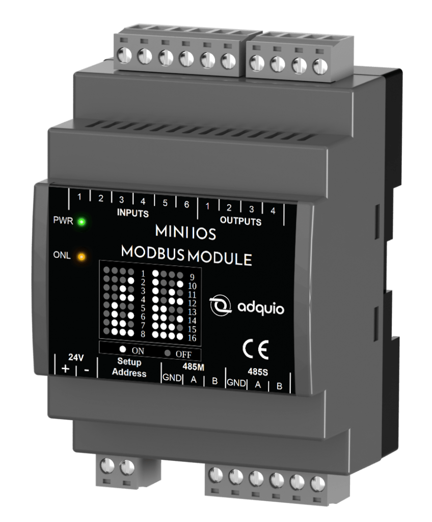
Adquio Mini IOs
Add digital inputs and outputs where you need them, connected to the installation’s bus.
6 digital inputs · 4 digital outputs
When to choose it: To collect states and operate devices that require digital signals.
Relay switching
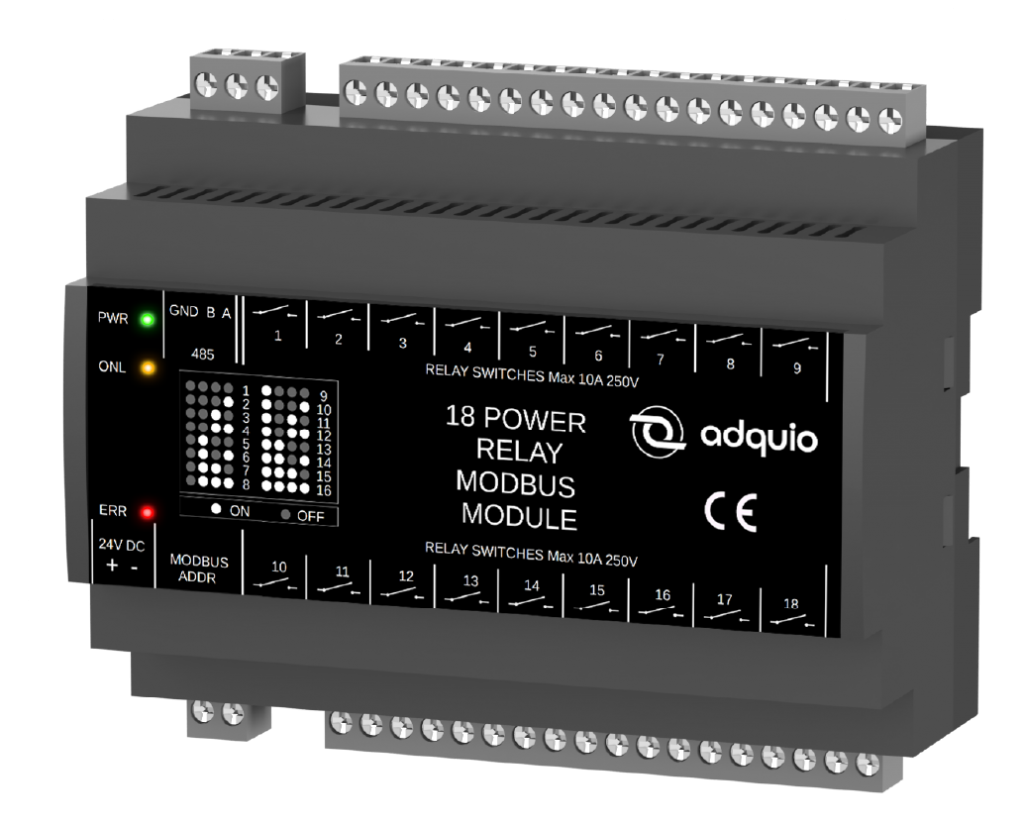
Adquio 18 Relay
Bring dry-contact circuit control together in a Modbus RTU module, reducing the need for individual relays and their control wiring.
18 dry-contact relay outputs
When to choose it: For lighting circuits, pumps, extractors or other equipment switched through a relay.
Analogue signal acquisition
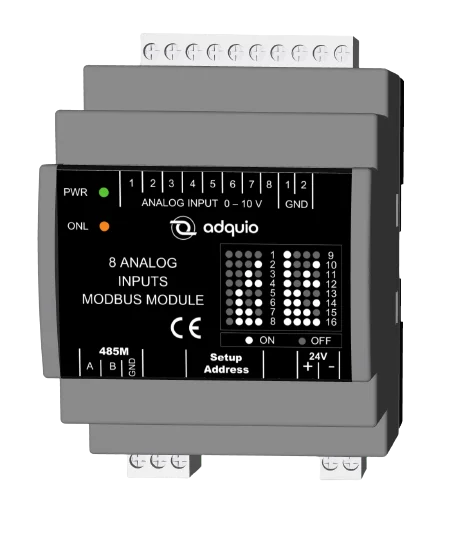
Adquio 8 Analog Inputs
Collect signals from 0–10 V sensors and transducers and send their measurements to the controller for use in logic and supervision.
8 analogue 0–10 V inputs
When to choose it: For pressure, flow, level, humidity or other measurements provided through a compatible signal.
Analogue regulation
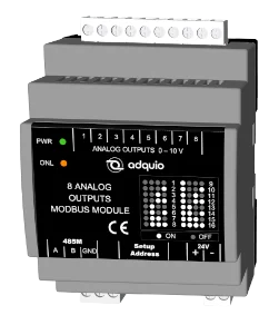
Adquio 8 Analog Outputs
Add 0–10 V control signals to regulate compatible actuators, such as proportional valves, fans or dampers.
8 analogue 0–10 V outputs
When to choose it: When you need proportional regulation of equipment, as well as switching it on or off.

Temperature measurement
Adquio 8 PT1000
Expand temperature acquisition with two-wire PT1000 probes and use their readings to control the installation.
8 two-wire PT1000 inputs
When to choose it: To measure temperatures in rooms, ducts, pipes or equipment using the appropriate probe.
Which expansion do you need? Start with the signals.
Compare what each module provides. All models in this table communicate with a compatible master through RS-485 and Modbus RTU.
| Module | Analogue / configurable inputs | Dedicated digital inputs | Digital outputs | Analogue outputs 0–10 V | Relays | PT1000 inputs |
|---|---|---|---|---|---|---|
| Adquio Multi IOs | 8 configurable A/D | — | 4 | 4 | 5 | 4 |
| Adquio Multi IOs Pro | 7 configurable A/D | 10 | 10 | 7 | — | 4 |
| Adquio Mini IOs | — | 6 | 4 | — | — | — |
| Adquio 18 Relay | — | — | — | — | 18 | — |
| Adquio 8 Analog Inputs | 8 at 0–10 V | — | — | — | — | — |
| Adquio 8 Analog Outputs | — | — | — | 8 | — | — |
| Adquio 8 PT1000 | — | — | — | — | — | 8 |
A/D means analogue or digital. In Multi IOs, the 8 configurable inputs are used according to the selected signal; they are not 8 analogue inputs plus another 8 digital inputs. In Multi IOs Pro, the 7 configurable inputs are in addition to the 10 dedicated digital inputs.
Digital outputs and relays have different functions. Transistorised digital outputs are not dry contacts. The “—” symbol indicates that the module does not include that function.
Current signals: use the appropriate adapter to connect a 4–20 mA signal to a 0–10 V input. PT1000 inputs are for two-wire probes.
From field device to control interface
The expansion provides physical connections. The controller uses the signals and shares them with the interfaces and platforms chosen for the project.
01 · FIELD

Measure and act
Probes, contacts, sensors and actuators provide or receive signals from the installation.
02 · EXPANSION
Adapt the signals
The module connects the physical inputs and outputs. RS-485 and Modbus RTU carry the data to the controller.
03 · CONTROL
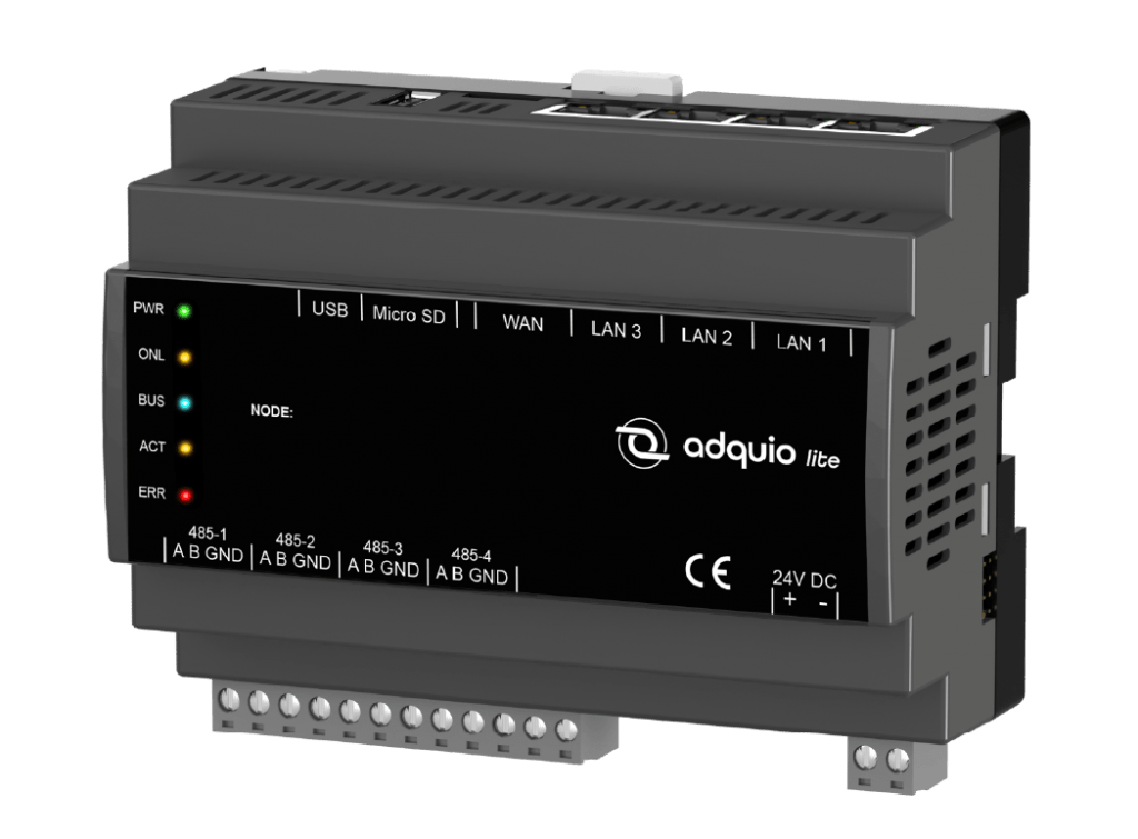
Run the logic
The controller collects variables, coordinates equipment and executes the project’s program.
04 · OPERATION
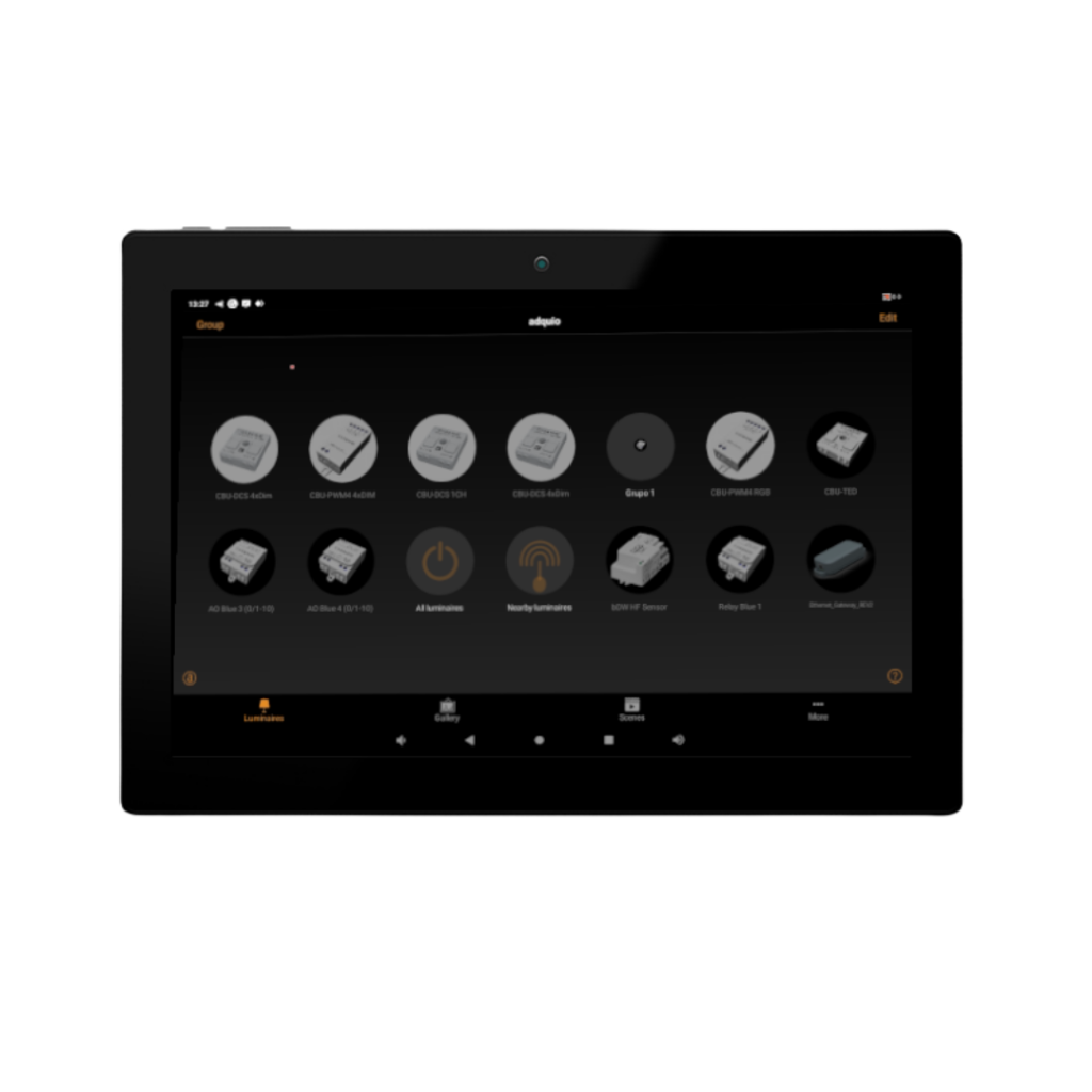
Visualise and supervise
Screens and platforms display states and measurements and allow users to operate the installation.
Connect each module to a Modbus RTU master through RS-485. Choose a controller with the right ports, assign unique addresses and configure the bus. To centralise from a device without a local RS-485 port, design the communication with the controller that collects the field signals.
Modules that meet field requirements
Choose the signal and its function first. Then combine modules to cover the measurement and control points of each device, zone or control panel.
HVAC and machinery
Combine temperatures, states, relays and proportional signals to integrate HVAC equipment.
Circuits and digital signals
Switch circuits through relay contacts or add digital inputs and outputs according to the signal type.
0–10 V measurement and regulation
Collect measurements from sensors and transducers and send regulation signals to compatible actuators.
Temperatures at more points
Send readings from two-wire PT1000 probes to the controller for climate logic, visualisation and historical data.
An expansion properly integrated from commissioning
The number of modules a project supports is not just a matter of counting addresses. Sizing considers the bus, equipment, communications and required operation.
01
Define the signals
Count the inputs and outputs by type, their ranges and the function of each point.
02
Size the bus
Review the connected equipment, wiring, power supply, termination and reading frequency.
03
Configure the variables
Set the address and communication parameters. Use the configuration guides available for each module.
04
Test the result
Check readings and actions, then bring them into your screens, alarms, logic or dashboards.
Documentation to move from design to the control panel
Keep the module’s product information, variable configuration and commissioning resources at hand.
Product pages
See the product page of each of the seven modules for connections, signal types and specifications.
Brochures and documentation
Access the commercial brochure library and the ecosystem datasheets to prepare your project.
Configuration for Adquio
Find the published examples and variable files for modules that have a configuration guide.
Complete the architecture with screens and interfaces, Adquio Supervisor, Adquio SCADA, Adquio Cloud BMS and Adquio Analytics, according to the operation and analysis your installation needs.
EVERY SIGNAL HAS A PURPOSE
Let’s design the expansion your installation needs.
Tell us which equipment you want to connect, which signals it uses and where the modules need to be installed. We will help you define the expansions and control architecture.
